Lesson 1
1 Learning Objectives
By the end of this lesson students will be able to:
- Define control system, system law, transfer function, system properties
- Explain how engineers and scientists approach systems
- Define open loop and closed loop control system
- Define input/reference, controller, summing junction, process/plant, output/controlled variable
- Draw a block diagram of a system given a description
2 Systems
A system converts inputs to outputs. Inputs can be voltages, chemical species, forces, displacements, and so on. Outputs are the same. Inputs and outputs should be quantities that you can measure (i.e., that have units). Components inside the system convert the inputs to outputs and can be resistors, capacitors, springs, gears, levers, chemical reactions, etc.
The components inside the system are modeled by equations called laws. The equations have constants that are called properties. All systems can be represented by a block diagram, which has the pattern of:
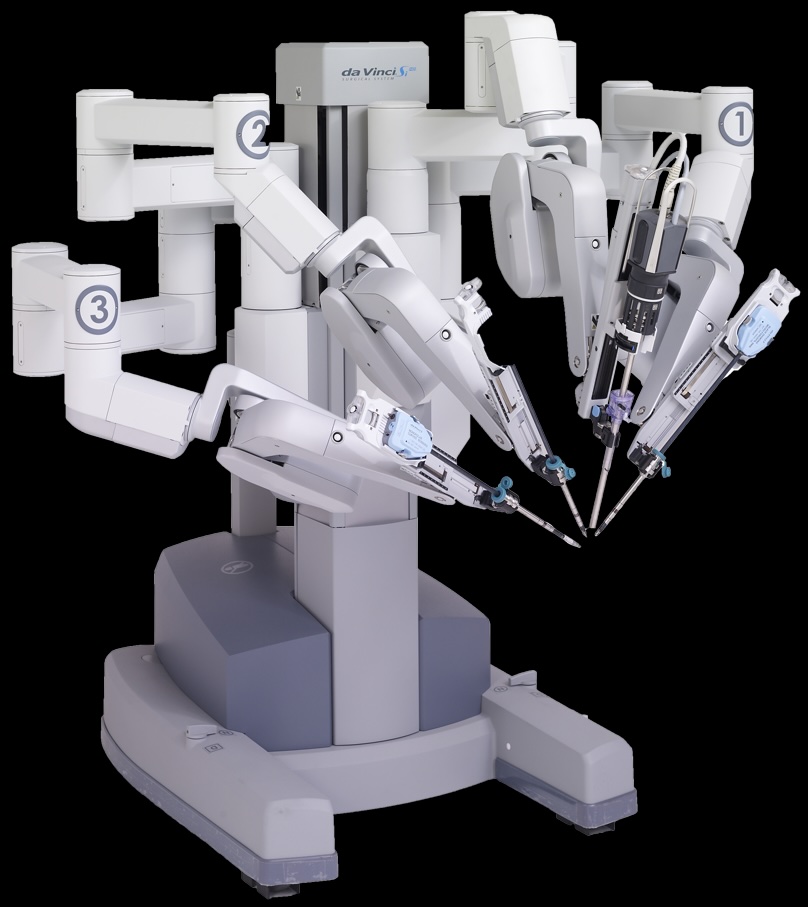
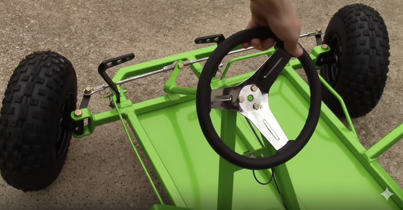
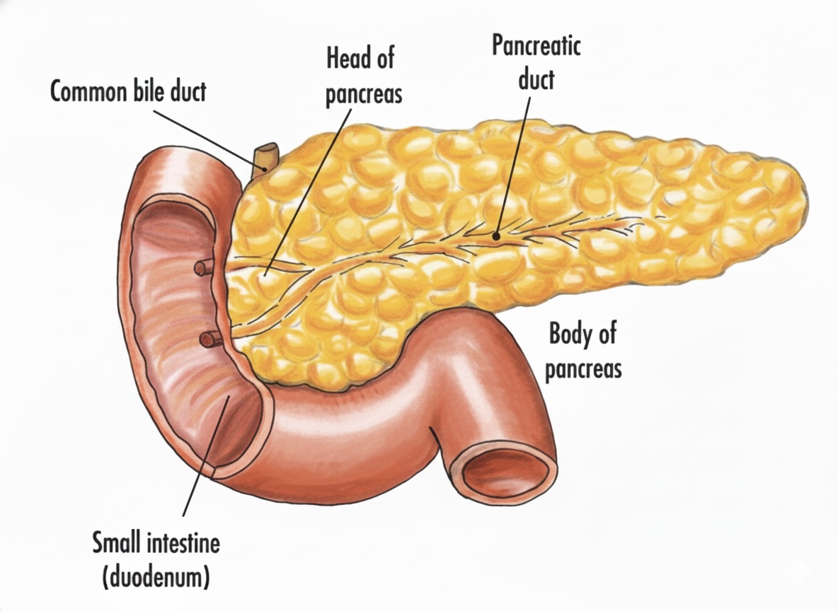
Student Exercise 1: Sketch a block diagram of each system shown below.


3 Looking at Systems from Different Vantages
There are a couple of ways to think about systems. Engineers are typically concerned with designing systems from scratch. Their job is to pick components and assemble them so that the system will give specific outputs for certain inputs. In contrast, scientists are often interested in giving a system inputs and measuring the outputs with a goal of figuring out what components are in the system. Engineers design and build watches using a pile of parts; scientists look for watches in nature then try to figure out how they work.
4 Thinking About Systems
- We want to develop the skill of thinking about systems in terms of (1) input, (2) system law, and (3) output.
Imagine a small room that contains a spring attached to its ceiling. The spring can only move vertically. If a person applies a force, , to the spring, it will stretch by an amount . This is a simple system in which the input is and the output is .
What is the system law that relates input to output?
The force generated by the spring, , is proportional to its displacement. This force is equal and opposite to the applied force.
At equilibrium and , so or rearranging .
The block diagram for this system would look like:
In other words, the input times the system law gives the output. The system law, , is called the transfer function of the system because it relates inputs to outputs.
5 Control Systems
A control system is a collection of subsystems that produce a desired output for a given input.
As a concrete example, consider a central home heating unit. The input is the temperature you set on the thermostat. The output is the house temperature. The system is the thermal properties of the house. The control system will work to match the output to the input.
Graphical responses of the system are crucial to understanding its behavior. Let’s assume the house is initially at 68 °F and you adjust the thermostat to 75 °F. What would a plot of the house temperature, , look like over time?
5.1 Open Loop Systems
Control systems come in two configurations: open loop and closed loop. To continue with the analogy of a home heating unit, imagine you are in a house and the only source of heat is a large space heater. On the space heater, there is no temperature control, just On and Off. What does the block diagram of this system look like?
Two drawbacks of open loop systems: (1) they cannot correct for disturbances and (2) they do not know when the desired setting is reached. In the case of the space heater, it applies constant heat regardless of how hot the room gets.
- Block diagrams may have more or less blocks than what is shown above. It’s up to you, as an engineer, to figure out how many blocks they have and in what configuration.
5.2 Closed Loop Systems
Systems with these configurations are also called feedback control systems.
Let’s assume you upgrade your home and you now have a central heating unit with a thermostat on the wall. What does the block diagram of this system look like?
Student Exercise 2: A temperature control system operates by sensing the difference between the thermostat setting and the actual temperature and then opening a fuel valve an amount proportional to this difference. Draw a functional closed-loop block diagram of the system, identifying the input and output transducers, the controller, and the plant. Identify input and output signals of all the subsystems.
6 Controls in Biomedical Engineering
We can use control systems two different ways in BME:
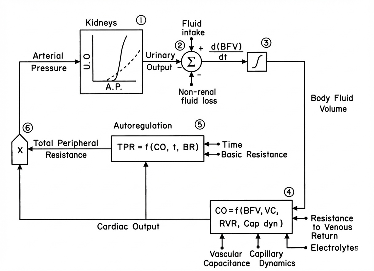
6.1 System Analysis
In BME, the systems we are most often interested in are physiological. Biomedical engineers create mathematical models of physiological systems using control theory. Then they perform experiments to validate, and if necessary update, their models.
6.2 System Design
Biomedical engineers address clinical needs by designing drugs or medical devices. They use concepts from electrical, mechanical, and chemical engineering to create systems that have a desired behavior.