Lesson 15
1 Learning Objectives
By the end of this lesson students will be able to:
- Explain the difference between first- and second-order transient system responses with and without feedback
- Explain the effect controller gain has on system output for first- and second-order systems
- Calculate the output and/or transfer function of a system with feedback and a disturbance
- Calculate for first-order systems with feedback
- Calculate the steady state value for first- and second-order systems with feedback and a disturbance, given a step input
2 Introduction
We learned how to build equations that represent systems; about transient responses; and about frequency responses. Now we combine everything we have learned so far and look at how closed-loop control systems compare to open-loop systems. We explore these ideas through an example application.
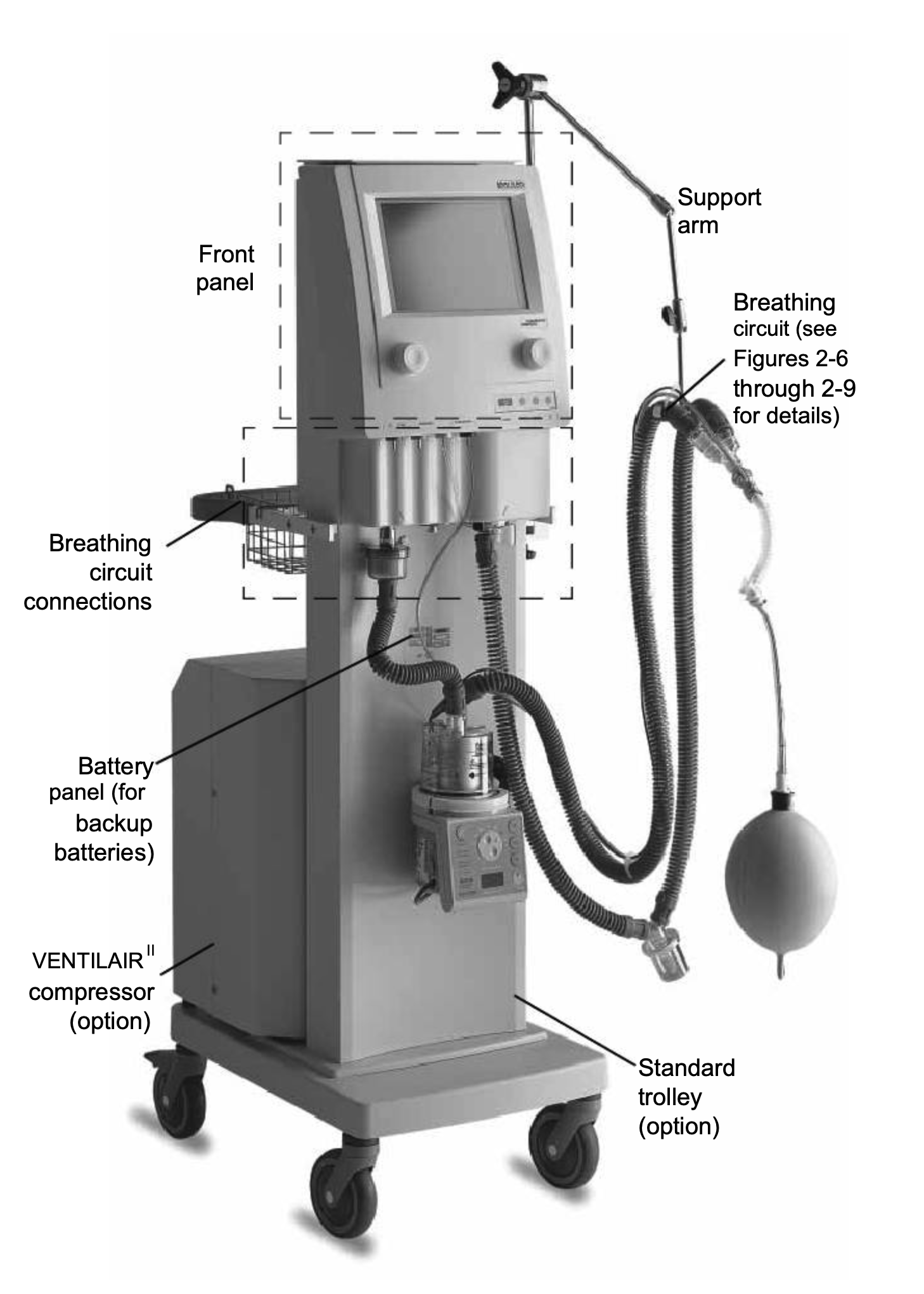
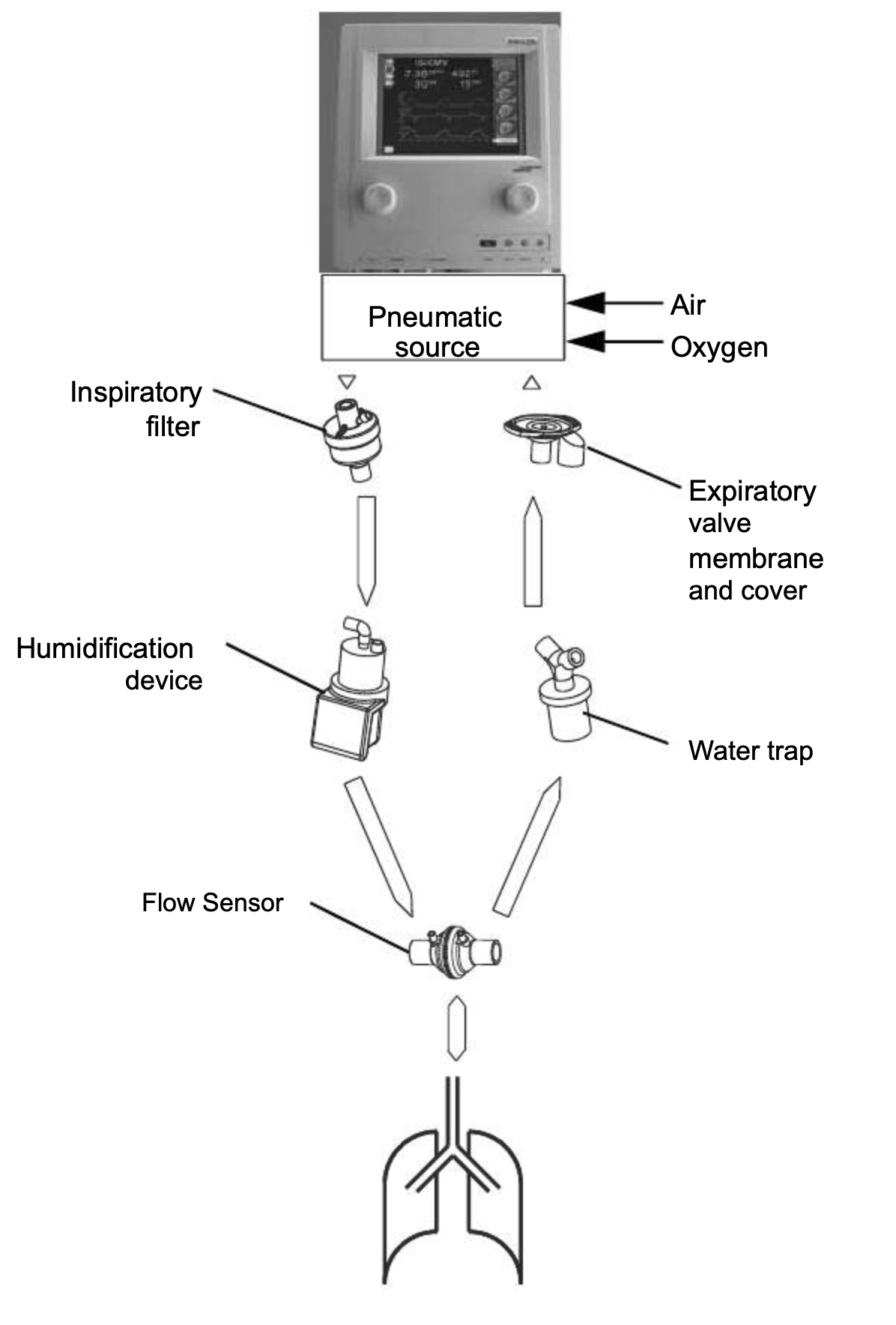
3 Designing a Mechanical Ventilator
Suppose we want to design a mechanical ventilator, similar to the one shown in the figure below. A mechanical ventilator periodically forces air into the lungs of a patient who is unable to breath on their own. While this might sound like a trivial task, it is very easy for mechanical ventilators to damage patient lungs, also known as barotrauma (about 3% incidence). Barotrauma results when too much air is forced into the lungs and one or more alveoli rupture.
There are a couple of issues for the design engineer to consider:
- How much air should the ventilator pump into the lungs? Too much and the lungs can suffer damage; too little and the oxygen levels in the patient will get dangerously low.
- What happens if the patient has a medical condition (e.g., asthma) that temporarily alters the resistance of the airways? Or what if there is a small leak in the tubing? How do you design a device to account for potential disturbances?
We can use control systems theory to model a mechanical ventilator and the lungs and look at the effect of different scenarios on device performance.
3.1 Student Exercise 1
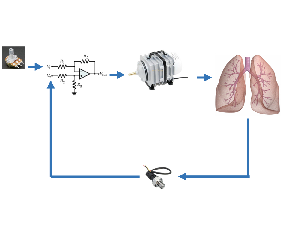
Draw two control system diagrams. The set point (input) is a voltage. The system output is pressure in the lung. One system should be open-loop and the other should be closed-loop. Include a controller, controlled system, and gain on the feedback loop for the closed-loop system. Allow for disturbances at the input of the patient’s lungs.
How does a closed loop system look in terms of physical components?
We now take these systems and see how they respond if the system is first-order versus second-order.
4 First-Order Model
The lungs are analogous to balloons. Their capacity changes as the pressure changes, so they can be modeled as capacitors. Air entering and leaving the lungs experiences resistance from the esophagus and bronchi, which can be modeled as a resistor. The above paragraph describes a first-order system (i.e., an RC circuit). Assume a voltage (pressure) input. Think about a single tank fluidic system.
4.1 Student Exercise 2
Draw the circuit.
4.2 Transfer Function
The transfer function from this circuit will go in the “lungs” block of the control system. Derive the transfer function if the system output is pressure in the lungs and the system input is the pressure generated by the controller.
4.3 Student Exercise 3
Derive
4.4 Open-Loop First-Order System
4.4.1 Student Exercise 4
Redraw the open-loop system. Write an equation for the output of the system.
4.5 Closed-Loop First-Order System
4.5.1 Student Exercise 5
Redraw the closed-loop system. Write an equation for the output of the system.
4.6 Student Exercise 6
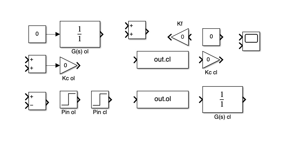
Compare the responses of the open- and closed-loop systems in Simulink. Use the ODE45 solver. Assume a step input of magnitude 1, cmH20 sec/L, L/cmH20, , , and . Write the steady-state value and time constant for the open-loop and closed-loop systems below. What differences exist? Run the simulation again with . Note any differences.
4.7 Disturbances
Disturbances are inputs that may affect the system. How does a disturbance affect a first-order system with and without feedback?
4.8 Student Exercise 7
In the model you used in the previous exercise, add a disturbance that is a step input of magnitude -0.5 and delay the disturbance by 0.75 seconds. The disturbance simulates a negative pressure, and could represent a leak in the tubing, for example. Set and run both models. What effect does the disturbance have in each case? Set . How does this change the responses to the disturbance?
4.9 Summary of First-Order Systems
- Feedback decreases the time response
- Feedback introduces a steady-state error
- An increase in gain increases the output of an open-loop system but reduces steady-state error in a closed-loop system; we cannot eliminate steady-state error completely
- Feedback and high gain reduce the impact of disturbances
Be sure to save your models. We will continue using them.