Lesson 5
1 Learning Objectives
By the end of this lesson students will be able to:
- Create transfer functions of compartment models
- Create transfer functions of hydraulic systems
2 Compartment Models
Compartment models are also known as lumped models because we assume that the substance (mass) is evenly distributed, or “well-mixed” throughout the compartment.
Compartment models are often used in pharmacokinetics because they provide good estimates of the behavior of drugs within the body.
There are three implicit assumptions when using a compartment model:
- The volume of each compartment is constant.
- Any mass entering the compartment is instantly well-mixed, or evenly distributed throughout the compartment.
- The rate of loss of mass from a compartment is proportional to the amount of mass within the compartment.
Here is a simple compartment model:
The way we write the DEs for these systems is to perform a mass balance on each compartment.
2.1 Example 1
Given: A compartment model in which the routes of clearance for radioactive iodine (I131) are uptake by the thyroid and excretion through urine.
sec and sec
Required: Find a transfer function that relates the injection of a dose to the mass of radioactive iodine (I131) tracer in the body:
2.2 Student Example 1
Given: A two compartment model for the distribution of creatinine in the body. One compartment is blood plasma. The other compartment is the rest of the body.
sec-1 L
sec-1 L
sec-1
Required: The transfer function where is the concentration in compartment “other”. Use MATLAB to find the answer.
3 Fluid/Circuit Equivalents
Fluids are:
- liquid (hydraulic) - incompressible, or
- gas (pneumatic) - compressible
Fluid flow through blood vessels (or pipes, etc.) is analogous to current flow in electrical systems. Pressure is analogous to voltage. Because of the similarity, there is a fluid equivalent of Ohm’s law. We can use circuits as a way to model fluid flow behavior, even though we’re not dealing with electricity.
3.1 Resistance
Consider the pipe shown below and assume that fluid is flowing through it at a volumetric flow rate, .
The volumetric flow rate creates a pressure drop, , as it flows down the pipe, which has a resistance . The resistance of the pipe depends on pipe geometry and fluid viscosity, . The equation for calculating pipe resistance is
- The resistance formula is valid for laminar flow only. To determine if flow in a pipe is laminar, calculate the Reynolds number: Re=, where is fluid density, v is fluid velocity, L is the length of the tube, and is fluid viscosity. If Re < 2100, the flow is laminar.
3.2 Capacitance
The change in volume of a container as fluid pressure changes is called fluid capacitance. It is a way to quantify the ability of the fluid system to store energy.
Fluid capacitance is calculated by
where is change in fluid volume and is change in fluid pressure.
Capacitance typically appears in one of three configurations:
The first two are easy to understand. What about the third?
The pressure in the bottom of an open tank changes as the height of the fluid changes and can be written as
Converting to a differential format gives
Simplifying gives
The capacitance in fluid systems has the same relationship to pressure and flow that capacitance in electrical systems has to current and voltage:
3.3 Inductance (Inertance)
Fluid inertance is analogous to inductance in circuits. Moving fluid has inertia.
Pinch hose. Let go. Feel kick. Inertia.
The equation for inertance is
where is change in pressure and is change in time rate of volumetric flow rate.
The inertance in fluid systems has the same relationship to pressure and flow that inductance in electrical systems has to current and voltage.
3.4 Sources
In fluid systems, sources can be constant pressure (analogous to a voltage source) or constant volumetric flow rate (analogous to a current source).
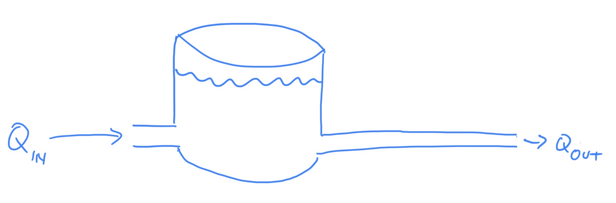
3.5 Example 2
Given the hydraulic system shown below, find
Assume: ; m/s2; kg/m3
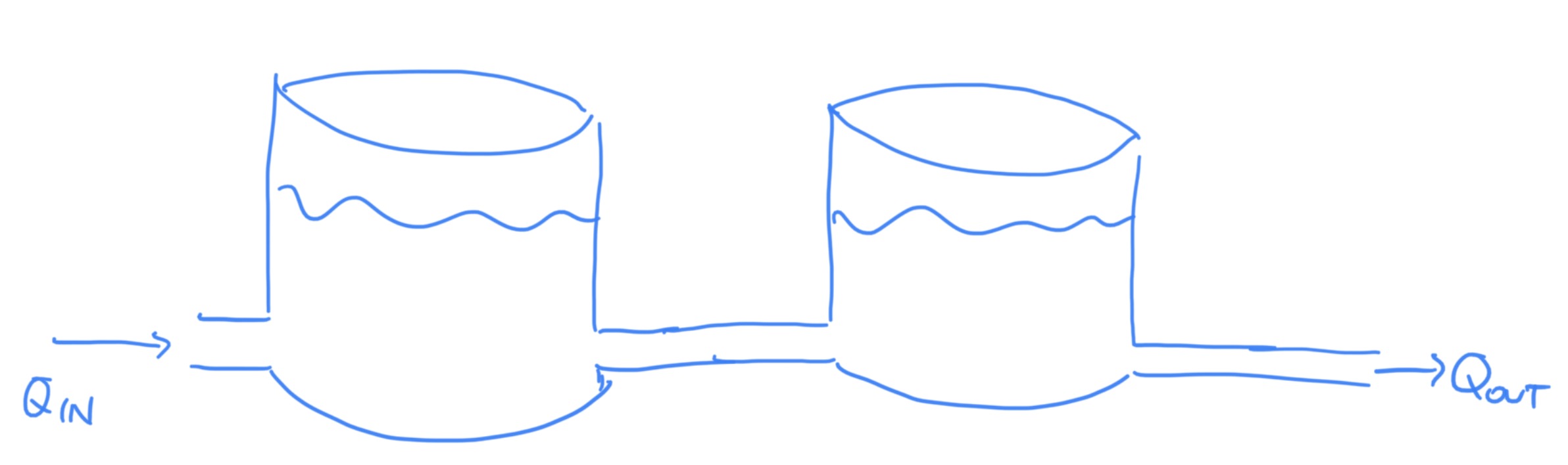
3.6 Student Example 2
Given he hydraulic system shown below find
Assume: ; m/s2; kg/m3
4 The Big Picture
Recall the diagram for a control system: